Palantir – Part 3
Breadboarding
Assuming nothing has gone pumpkin-shaped, you should now have a net-enabled Arduino without sensors or ability to do anything useful. Time to start plugging things in. We'll do this on a breadboard first as it's a good way to test the sensors are working and check polarities. Also, unless you're very experienced (in which case you've finished this project already and are happily developing a gravel cleaning robot), it's a good practise to get the electronics working before you break out the solder. We'll start by wiring up the lights, buzzer and switches.
Achtung! Achtung!
If you check the sketch, you'll see that the following digital pins are defined: ALERT_LED = 8, ALERT_LED_2 = 7, ALARM_BUZZER = 6. All these are set as outputs, so they're normally low (0v) but will go high (< 5v) to indicate various status messages. 5v is too much for an LED so we'll include current limiting resistors to reduce it (not actually required since the Arduino digital outs are limited to about 100mA and can't burn out an LED, but hey it's good practice. Also, our parenthesesed asides seem to be getting longer - must be old age or something).

Pin 6 can do PWM, which means it can be set to any of 255 steps between 0 and 5v. Feeding a lower voltage to the buzzer reduces the volume (if you're still above the buzzer's minimum cut off), we'll also stick in a toggle switch so you can turn off the noise during debugging.

Finally we'll stick in a momentary 'press to make' button to pull the RESET pin to GND. That resets the Arduino and the Ethershield - or rather it should but a bug in the rev1 shield means that it often won't and you'd have to reset it manually. Adding a small capacitor across the button (mostly) fixes this, although if it's value is too high you'll find the 'auto-reset before upload' feature of the IDE will stop working. We suggest 33 or 47 nF as being just right.

Before we start putting in any sensors, lets set up the power supply lines. There are two of these, a constant 5v line at the top of the breadboard and a digital pin 9 supplied line (at the bottom). This second line is normally low (off) to saved power but will be brought high (on) just before the analogue sensors are read, before being returned low. The DS18B20 sensors are constantly powered but use minimal energy unless actually reading temperatures or communicating with the Arduino.

So having built all this, lets power up and load the Palantir sketch (if you haven't already). Assuming everything starts up ok, it should beep crazily and flash the red LED at you every 30 seconds or so. If you watch the Serial output you should also see complaints about being unable to find any temperature sensors. This is a fatal error for Palantir because the OneWire line doesn't always start up correctly on first power on and we need to alert you to this. Pressing the reset button at this point should reboot both the Arduino and the Ethershield. Once it has, also check for a connection green light on the Ethernet socket (assuming something is plugged in!) Assuming everything is ok, lets move onto adding a temperature sensor.
I haz a flavor, er, temperature
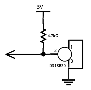
We'll connect up a single DS18B20 sensor first, so grab one and first check the polarity. With the flat face upwards the pins are (from left to right), 1 - GND, 2-signal, 3-optional power in. Palantir runs these sensors in 'parasite power' mode, where the signal line is 'pulled up' to a few volts (using a 4.7kΩ resistor) and the sensor charges a small internal capacitor off this to use while communicating. Thus pin 3 isn't needed and should also be connected to ground.
If you power up again, you should no longer get the alarms and in the Serial output you should see the unique ID of the sensor (note this down). Palantir will then start looping, reporting the sensor temperature every 20 seconds or so, along with its attempts to POST this data to the server (which should fail with an authentication error). If the sensor isn't found, try resetting, then a power cycle, then check your breadboarding!
Once you've got this working, you can try adding a second temperature sensor in parallel with the first - just plug it into the next row down on the breadboard.

And the rest
We'll set up and test each of the sensor types individually.


Pressure
The light and Hall effect chips can be directly inserted into the breadboard but the pressure sensor needs an adaptor cable of some sort. If you check the specs you can see that the MPX5010DP uses a '867C-05 unibody' casing - we only care about this since it defines the order of the pins: 1 (marked by a notch) signal, 2 GND and 3 power in (pins 4, 5 and 6 should be ignored). You can solder wires on directly but a neater approach is to use a standard 3-wire PC fan plug. This matches the pin spacing and gives you wires that can be plugged into the breadboard. Alternatively you can hook up via a jack plug and socket. As previously defined in the sketch, the signal line should be connected to analogue pin 0 on the Arduino.

Hopefully now once you power up the Arduino again, you should see a P0 pressure reading being reported to the Serial output. You'll also probably see values for L0 and H0 despite not having sensors connected for these. This is because the associated pins have been left 'floating' and hence the Arduino picks up random readings off them. You'll notice that these values jump around a great deal between cycles.To test that the pressure sensor is working, attached a short length of air tube to one of the ports and try sucking/blowing on it. It should be obvious which one is the -ve pressure side so make a note of it. If you have the kit to hand, you could also try hooking up this port to the Venturi of a suitable filter or powerhead - that'll give you some real data.
There's a couple of minor risks that need to be considered here. If the main water flow gets obstructed (e.g. by an excessively adventurous ancistrus) then water may get pushed back up the Venturi line. It's unlikely that water will actually get into the sensor, but if the line detaches off the sensor port your filter may then start pumping water out of the aquarium. Adding in a non-return valve just above the water level stops this and also gives protection for the sensor against humidity. Unfortunately these valves significantly reduce sensitivity (since a low Venturi pressure can't open them) and may give false positive readings. Hence on smaller or low flow rate filters we suggest omitting the valve and just using a tube jointing insert in its place. This should pop open under pressure before the connection to the sensor does.
Light
We detect light by measuring at the voltage split between the LDR and the 47kΩ resistor (note that neither component has a polarity). As the light level increases, the LDR resistance fall and the voltage across the resistor becomes a larger % of 5v. This in turn gives a higher reading on analogue pin 1.

Set this up and test it as above, you should be able to detect a hand being places over the LDR.
Hall effect
This one's a bit more fiddly to set up and test. The A1301 sensors we want use a 3-pin 'SIP' mini transistor-like casing. With the larger flat face away from you and the legs downward, then the pin ordering is: 1 power-in, 2 GND, 3 signal. Connect this up to analogue pin 2 on the Arduino and go find a small magnet.

Readings off the Hall effect sensors are very small (normally sub 100) but if the Arduino is monitoring the sensor correctly, you should now have a stable low value that varies very little. If you then waggle a small bar or neodymium magnet near the face of the sensor, you should get an increase in value roughly equivalent to speed of magnet movement.
If you want to test the Hall sensor more rigorously, you'll need to break it out onto a longer cable. It's a very small unit to try and solder to, so we'd suggest either using a small 3-pin plug (a fan plug is too big unfortunately) or a small chunk of stripboard. If you try the latter, keep the leads long since you'll have to bend the sensor over to lay its flat face against the object to be monitored. Once you have it on a longer cable, try holding it to the top surface of a external filter. You'll get the highest values near but just off to the side of where the impeller is. This will probably take a bit of experimentation.
So, now you have a breadboarded Palantir and it should look something like this:

Let's get it talking to the world!
Footnote: the Fritzing (amazing software!) files for these diagrams: arduino_outline, palantir_steps
Comments