Palantir – Part 2
February 8, 2011
Boards, sensors and stuff
So what do you need for building an aquarium monitor (apart from a large crystal sphere)? Let’s start with the following boards – prices are approximate minimums (plus VAT) for the UK as of Jan 2011:
- Arduino – either an Uno (£22 from e.g. Cool Components) or a ATMEGA328 Duemilanove (clones are about £12 from Ebay)
- Wiznet W5100 based Ethernet shield – we’re using a cheap clone of the rev1 but rev2 should also work (and should have the reset bug fixed). Prices vary from £23-35 depending on the source. Avoid the very cheap ENC28J60 Ethershields, they use a different library so you’d have to recode the communication
Also there are rumours of an Ethernet enabled version of the Uno being released at some point. Might be worth keeping an eye open for it as a single board would probably be cheaper.
Communication What you need connectivity-wise will depend on your home network. If you’re close enough to a router/switch or your ADSL modem, then you can probably just plug into that. Otherwise you could use a WiFi repeater, a range extender or a pair of Powerline/Homeplug adaptors should they be going spare. We’ve has good experiences with the WiFi bridge from Open:media, which appear to be a re-brand of the original Vonets VAP11G. Needs a PC to set it up but once running they seem to be nicely reliable.
Power (overwhelming!) Both the Uno and the bridge have internal regulators and so can run off a range of DC voltage (6-12V or so for the Uno; even higher for the VAP11G). This means you can feed them off a scavenged wall wart if you don’t mind splicing on a suitable plug (watch the polarity!) Both will run off USB power though (5v) so it’s easier to use a Mains to USB charger, as supplied for mobile phones or whatever. Cost is about £4 off Ebay and make sure you either get 2x 500mA or a single 1000mA unit and a passive hub to split it.
Sensors Since these are mostly self-built, you’ll need to acquire a suitable length of high flexibility 2-4 core cable (e.g. phone cable or unwanted mouse tails) to connect them. Scavenging a load of PC fan (and similar) plugs will also make your life easier, as they make convenient blocks to mount the temperature and Hall sensors on. Otherwise you’ll have to solder carefully and keep all the legs insulated from each other.
- Temperature – Bare Maxim DS18B20 sensors can be bought from RS or Ebay and will cost £1.10-3.50 depending on source and numbers. These can be waterproofed with a couple of layers of shrink tubing (to be safe, soak in water for a couple of days before adding to the tank). Probe versions are available from SureElectronics but beware long shipping time – £3.50. You also need a single 4.7 kΩ resistor for the 1-wire bus
- Light – light dependent resistors are pretty much all the same – £2 for 5 or so. Each will also need a 47 kΩ resistor to do the voltage split.
- Pressure – Farnell carries the Freescale MPX5050DP (suitable for air pumps) or MPX5010DP (Venturi) sensors – £12 each. Depending on the filter, you may also need Venturi hardware (e.g. for Juwel filters – £8 from Ebay)
- Hall effect – we got Allegro A1301EUA-T sensors from Farnell – £1.50. Equivalents would also work but would probably require different calibration.
Other bits you may already have, can scavenge, or can get from your favourite web shop:
- LEDs – 1x red and 1x green plus 2x 270-350Ω resistors
- piezoelectric buzzer – (< £2) but it'll needs a wide input voltage range (e.g. 3-24V DC) if you want to effectively volume control it
- Momentary, push to make switch – (< £1) used for hard resetting the Arduino and Ethershield. If you have a rev1 board it's also helpful to add a 33 or 47 nF capacitor across it address the shield's reset bug, rev2 board hopefully don’t need this.
- Mini toggle switch – (£1) used to isolate the buzzer, so it doesn’t drive your house mates nuts. You only need a single pole/single throw but more than that won’t hurt
- Stereo jacks/sockets – (£0.5 each) used to connect the sensors (we used 3.5 mm but any size would do). You’ll need 7x sockets and 1x plug for each sensor, Ebay is a good source (or pinch your office mate’s headphones)
- Plumbing – 2m of air tube, 1x non-return valve per air/flow sensor (if you want to use them), 1x T-splitter per air sensor
- USB cable – the Uno uses the A to B ‘printer’ cable, clones may use mini or micro versions so check!
- Network cable – if you’re not using a WiFi bridge
- Copper strip board – (this stuff) you don’t need much, 5-6 inch2
- PCB pin strip – 0.1 inch separation, one row of 36 is enough
- Hook up wire – multi stranded and multi coloured is best!
- Box – cardboard, plastic, tupperware, whatever
Tools We’d suggest acquiring at least: a small breadboard, solid core jump wire, an electronics soldering iron, flux solder, pliers, side cutters, wire strippers and a multimeter. But you have all them already, right? :)
Setting up your Arduino
Before going further you’ll need to be reasonably familiar with the Arduino hardware, its programming IDE and how to set up, load and run sketches. We’ll only cover this very briefly as it’s not the aim of this write up, however the basic steps are (assuming you’ve got your hardware!):
- Setup – go here and follow your OS specific instructions for downloading the IDE and getting it chatting to the board
- First sketch – load and ruin the Blink program (cheer lots if it works)
- Breadboard – make sure you follow how its used!
- Further learning – play with some of the other test sketches, we suggest at least: DigitalReadSerial, AnalogueReadSerial & Fade
- Ethernet – with the Ethershield plugged on top of the Arduino and connected by wire to your router, get the simple Web client running. You’ll need to define a suitable MAC (make one up) and IP address (pick something unused but on the same local network)
That’s probably enough to let you get on building the monitor, but if you want to learn more see the Arduino site. Before we go further however, please collect together at least: 1x Arduino, 1x Ethernet shield, 1x small breadboard, 2x 330Ω resistor, 1x 4.7kΩ resistor, 1x 47kΩ resistor, 1x 47nF ceramic capacitor, 1x red LED (5mm), 1x green LED (5mm), 1x piezo buzzer, 1x mini toggle switch, 1x mini push button switch, 1x DS18B20 (temperature), 1x A1301EUA-T (Hall), 1x MPX5010DP (barometric pressure), 1x LDR (light), 1x CAT5 patch cable, and 1x USB cable (in a pear tree).
Pins and things
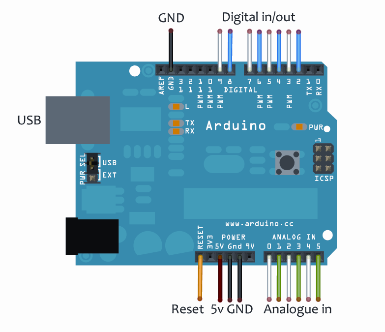
This diagram shows the pins we’ll be using for Palantir:

The row at the top (blue/white) are the digital pins, we only have access to some as the rest are needed by the Ethernet and serial communications. Digital lines can be read (in) or write (out), so can be used to drive LEDs, monitor the state of switches or communicate digitally with our temperature sensors. We can also use one of them to supply power to the analogue sensors – that way we can turn them off when not in use. The bottom row (green/white) are the analogue pins, these are read only and their applied voltage is converted to a 0-1023 ranged integer. These are used to monitor the pressure, light and Hall effect sensors. The reset pin will reboot the Arduino (and intentionally the shields, although this is buggy) when it’s briefly connected to ground (GND). The 5v line will be used to supply the temperature sensors.

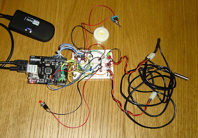
This is a ‘beta’ set-up for Palantir with a light and a couple of temperature sensors (yes, it’s a complicated mess!) The Ethershield is stacked on top of the Arduino, but since they have the same pin out to the breadboard you can ignore this. We’ll now step through the process of setting something similar.
Additional libraries
The key libraries are already part of the IDE (we built this with v021, so things may change) but you’ll also need to download and install (unzip to the /libraries/ directory) these:
- OneWire – communication library – local copy: v 2
- DallasTemperature – accesses the DS18B20 temperature sensors – local copy: v 3.7b
- PString – for simpler text formatting – local copy: v 2
- MemoryFree – to track SRAM usage – local copy:
- Flash – allows static text to be saved to Flash memory – local copy: v 3
Finally, carriy out this ‘free up some RAM’ hack: open file ‘/hardware/arduino/cores/arduino/HardwareSerial.cpp’ in a text editor. Find ‘RX_BUFFER_SIZE 128’ and change it to ‘RX_BUFFER_SIZE 16’, just below there change ‘int head’ to ‘uint8_t head’ and ‘int tail’ to ‘uint8_t tail’. Save the file and restart the IDE.
Palantir sketch
First step, grab the source code and save it into a new blank sketch. Check it compiles (but don’t upload) and if so, go looking for the following lines:
- #define ARDUINO_ID “xxx” – change ‘xxx’ to a short but unique identifier for your Arduino
- #define HTTPAUTH “xxx” – this will be your basic authentication string needed to send data to the server. Worry about changing it later.
- byte mac[] = {0xDC, 0xA9, 0xBC, 0xED, 0xF3, 0xE2}; – this is your MAC address (DC:A9:BC:ED:F3:E2). You can change it or leave it as it is but if you want to use a WiFi bridge then it’ll probably have to be registered on your router
- byte ip[] = {192, 168, 0, 33}; – this is your Arduino’s IP address. Set the first three numbers to the same as your PC, then the 4th as something unique. Register the address on your router’s DHCP settings so someone else doesn’t steal it
- byte server[] = {87, 194, 221, 47}; – this is pointing at www.fluffydragons.org, unless our domain gets moved…
- const int SERVER_WAIT = 3; – if your net connection is crappy and slow, you may have to increase this a bit
- const int LIGHT_SENS[] = {0}; – this means a light sensor is on analogue pin 0, change it to pin 1
- const int PRESS_SENS[] = {2,3,4,5}; – four pressure sensors defined here, change to just one on pin 0
- const int HALL_SENS[] = {1}; – one Hall sensor, change to pin 2
- const int THERM_COUNT = 5; – sets the maximum number of temperature sensors, leave it alone
- const byte ALARM_VOLUME = 4; – sets the alarm volume (if your buzzer can handle it)
Now check everything compiles ok. Upload it if you like, you’ll probably get lots of angry blinkenlights. So, on to breadboarding….

Leave Your Comment